Automated Control for High Power Testing
Laboratory tests are essential in the development and testing of components for energy supply networks. In addition to highest precision for the challenging measurements synchronous control of the complex test procedures is also crucial to the quality of the test results. In order to achieve this AMOtronics combines transient recorders and so-called sequencers in an integrated system.
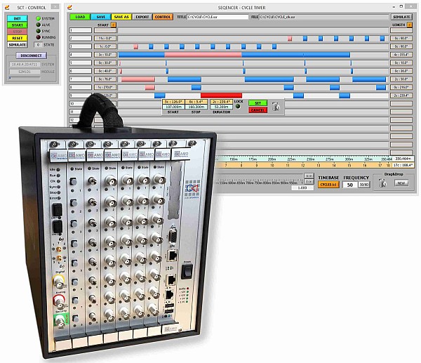
The sequencer (timer) monitors the test facility and at the same time controls the unit under test in real-time. Measurement signals as well as external control signals are processed continuously and the control outputs of the sequencer are switched accordingly. In parallel the transient recorder acquires both the measuring signals as well as the input and output signals of the sequencer. During the subsequent data analysis this allows the engineers to gain a detailed insight into the test procedure and the action and reaction between the test facility and the unit under test.
A current application of this solution can be found at the governmental Korea Electrotechnology Research Institute KERI in Changwon, South Korea. In addition to the modernization of the existing test facilities the Korean engineers also decided to use AMOtronics technology for the extension of their high-performance lab. After the implementation in 2015, the 4,000 MVA high power laboratory with eight test cells is one of the world's largest testing facilities for high power switch gear (e. g. circuit breakers).

SATURN Test Sequencer / Cycle Timer
(Example in medium-size Saturn Cube housing with electrical and optical inputs and outputs)
Safe optical transmission of measuring and control signals
At KERI several SATURN systems from AMOtronics are responsible for data acquisition and control. Like the measuring signals also the control signals are being transmitted via fiber-optic cables. The optical transmission effectively protects the signals against interferences from strong electromagnetic fields in the test cells. The SATURN system automatically compensates the varying signal propagation delays which result from the different distances in the widely-branched network of three generators, eight test cells and two control rooms.
Flexible interconnection between generators, test cells and control systems via optical routers (matrix switches)
A special part of the solution are intelligent optical routers (matrix switches) provided by AMOtronics. The easy-to-use control software graphically represents the individual setup of the test site. The software allows the operators to easily interconnect the various measurement and control units with test cells and generators, just as needed for the individual test procedures. In addition the AMOtronics solution also allows the bundling of up to 64 digital control signals in a single fiber optic cable. This minimized the number of necessary cables and substantially reduced the time, effort and costs for the system installation.

High-speed Matrix Switches for software-controlled routing of optical signals between control room and test cells, combined with Fiber-Optic Conversion Units as the interface between bundled optical transmission lines and either 32 or 64 separate optical switching signals
Synchronized data acquisition and control using the generator frequency
In order to synchronize control and measurement on the exact signal phase the AMOtronics systems enable the integration of the generators either classically in analogous way as well as by means of a digital reference signal. At KERI each rotation of the generator shaft produces 720 digital pulses for exact synchronization. Thanks to the precise determination of the phase angle for example AC switches can be switched exactly at the zero crossing point in order to protect the components from overload. As a different use case emergency switches must withstand the highest loads and therefore need to be tested at maximum power. Moreover, each system also provides analogue and digital connections for monitoring and controlling of peripheral equipment such as access locks or indicator lamps.
Summary
The combination of transient recorders and sequencers / timers coupled with intelligent optical signal transmission provided by AMOtronics enables the test laboratory to perform high-precision tests while increasing the efficiency and reducing the costs through a flexible use of available resources and lower installation costs.

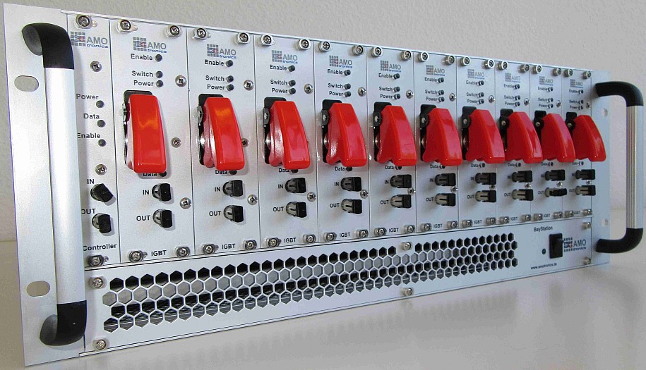
Optically controlled semiconductor relays (IGBT switches) from AMOtronics:
- control via optical signals (fiber optic cables)
- individual ON/OFF switching signal per channel
- common ENABLE signal per 19 inch unit
- additional manual switch per channel for on-site operation and manual testing


