Real-Time Trigger Prediction for Hypervelocity, Impact and Ballistic Tests
The SATURN Real-Time Trigger Prediction System simplifies experiments and tests conducted with accelerators, light-gas guns and other test facilities for flying objects. The system uses input signals from laser barriers, screens, foils, and other sensors to detect multiple positions of the flying object, calculates the velocity and predicts in real-time the exact moment at which the object will reach specific positions along its trajectory. Based on this information the system precisely triggers high-speed cameras, strobes, Flash X-ray and more to reliably record multiple flight positions, the impact, and other events of interest.
The system is based on a combination of a SATURN Transient Recorder and Sequencer and the Trigger Setup Manager (TSM) software. The specialized solution saves time and effort during preparation, execution and post-test analysis for hypervelocity, impact and ballistic tests. It can be equipped with different numbers and types of inputs and outputs - perfectly matching the intended tests and experiments.
In addition to flexibility and ease of use, one of the outstanding features is the "real-time trigger prediction". This function automatically determines the speed of moving objects and calculates in real-time the expected time of arrival at configurable positions. The system generates precisely timed trigger signals for cameras, flashes and similar test equipment, whereby the individual reaction time (delay) of each connected component can be taken into account. As for instance, the system allows to precisely trigger flashes and cameras microseconds in advance in order to reliably record the moment of interest.
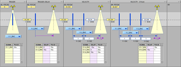
Trigger Setup Manager (TSM) software for multiple diagnostic positions with individual settings for
trigger generation method, input and the output signals with desired delays and pulse lengths
The system is modular and expandable. It is available in various housings from small portable systems up to multi-channel chassis for 19” rack mounting.
The system supports nearly any type of input signal. Users can choose between different types of analog inputs with measurement rates up to GigaSamples per second if needed. The system also supports up to 192 digital IOs (in/outputs). Up to 64 IOs can be provided as “local channels” directly in the main unit. Additionally (or alternatively) up to 128 IOs can be provided as “remote channels” in two subunits. Each subunit is connected with the main chassis via a robust high-speed optical cable. It allows to bridge long distances, as for instance between a bunker and the test field. A single fiber cable pair is sufficient to transmit up to 64 digital in/output signals between the main chassis and the subunit. During the test preparation this saves both time and costs.
A typical example are signals from light barriers and fragment test foils ("make screens"/"break screens"). Such signals can be measured either analog or digital. The use of analog inputs allows to perfectly fine tune the trigger conditions (level, dual level, pulse width, gradient). Digital inputs, on the other hand, simplify the hardware setup considerably and enable high channel counts at significantly reduced costs. A unique diagnostic function allows to check the correct connection and condition of make screens during test preparation and helps to avoid costly failed tests.
The same flexibility is also available on the output side. The spectrum ranges from common BNC outputs (3V TTL, 5V, 12V, 24V) up to isolated semiconductor switches for switching high externally applied voltages (e.g. for triggering X-ray flashes).
In addition the system can also be equipped with fiber-optic inputs and outputs. Both glass fiber (“ST”) and plastic fiber (“POF/Versatile Link”) are supported. The pure optical connection provides perfect isolation and protection from electrical interference. Its high transmission rate allows bridging of long distances while maintaining system-wide synchronicity across all channels.
The system comes with a convenient graphical software that dynamically adapts to the selected types of inputs and outputs. Regardless of their type, all inputs and outputs can be recorded as a single project. The measured signals can be displayed in various curve windows and analyzed in detail using cursor functions. If required, various export functions allow post-processing in any other software.
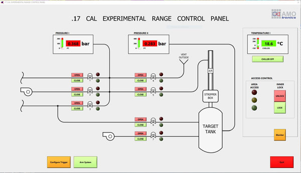
If needed the system can be provided with a custom user interface tailored to the test facility or firing range. This for instance allows to handle additional environmental sensors and actuators within the same system. A unique routing solution allows alternating operation of several test facilities from one control room.
Example of a custom user interface for operation of an accellerator.
The flexible hardware and software concept serves a wide range of different test scenarios and allows to adapt to rising demands. As for instance the system can be equipped with additional channels if the required type or number of inputs and outputs changes over time.
Key Facts of the Real-Time Trigger Prediction System
Hardware & Software
- Multiple independent diagnostic positions
- Trigger prediction in real-time (accuracy <40ns)
- Easy-to-use graphical user interface for block-wise trigger setup with different types of trigger blocks:
o INITIAL (start trigger)
o TRIGGER (immediate response)
o TRIGGER DELAY (delayed response)
o TRIGGER DELAY WITH FALLBACK (delayed response with fallback trigger input)
o VELOCITY 2P (trigger prediction based on 2 input triggers)
o VELOCITY 3P (redundant trigger prediction based on 3 input triggers)
o VELOCITY 3P 2x (redundant trigger prediction for 2 different target positions)
o INTERLEAVED (2 trigger delays nested into each other) - Support of various types of analog and digital I/Os
- Unique diagnostic features for trigger foils (make/break screens)
- Simple recording, saving and loading of signal data from inputs and trigger outputs as projects
- Comfortable display and analysis of signal data from analog and digital inputs and outputs in multiple curve windows with cursors and mathematical functions
- Customized user interfaces to handle additional environmental sensors and actuators within the same system
Inputs
- Expandable from 2 to 200 input channels
- Different types of analog inputs:
- from kS/s to GS/s
- standard and custom input ranges
- single ended / differential / isolated
- multiple triggers per channel
- Different types of digital input panels:
- 8x BNC 5V TTL, 24V, 48V
- 8x FIBER OPTIC ST (820nm)
- 8x FIBER OPTIC POF / Versatile Link (660nm)
- …
Outputs
- Expandable from 8 up to 192 trigger outputs
- Different types of output panels can be combined in one system:
- 8x BNC 3.3V / 5V TTL
- 8x 5V DRIVER BNC
- 8x 12V DRIVER BNC
- 8x 24V DRIVER BNC
- 8x SOLID STATE SWITCH (ISOLATED) max. 700V DC
- 8x RELAY ON/OFF
- 8x RELAY ON/TRI/ON
- 8x FIBER OPTIC ST (820nm)
- 8x FIBER OPTIC POF / Versatile Link (660nm)
- 8x TRIGGER FOIL (MAKE / BREAK SCREEN)
- …
Additional components (optional)
- Converter box for TTL-BNC to fiber optics (ST/POF/Versatile Link)
- Converter box for fiber optics (ST/POF/Versatile Link) to TTL-BNC
- Converter box for fiber optics (ST/POF/Versatile Link) to IGBT/MOSFET/RELAY
- Semiconductor relay (MOSFET/IGBT) with fiber optic connector (ST or POF/Versatile Link) for High Voltage switching
- …
Reliably catching the moment of impact or any waypoints of flying objects during hyper velocity, ballistic and impact tests is a challenging task for the test engineer.
Supported by AMOtronics’ Trigger Prediction System, it’s easy!
Download the product flyer (PDF)


